
JA-111N
Service explanation for JA-111N
BUS signal output module PG
This product is part of the JABLOTRON JA-100 alarm system. It provides a switching contact of the output relay. It can serve, for example, to operate an electric door lock, blocking, indication, and the like. The relay can be controlled by a programmable output of the control panel, furthermore by the status of the section (armed = relay contact on), possibly by alarm in the section (alarm = relay contact on). The product is intended for installation by a trained technician with a valid Jablotron certificate.
Installation
The module can be installed in a JA-190PL (Jablotron) mounting box.
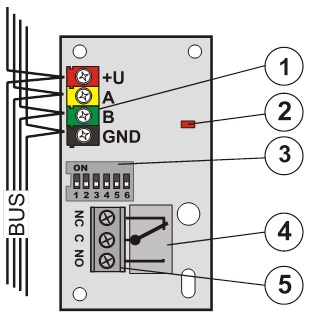
Figure: 1 – BUS terminals; 2 – red signal light of relay enabled, 3 – configuration switch, 4 – output relay, 5 – terminals of the relay.
1. Use the switch (3) to set the number of the output or section to which the relay is to respond - see setting tables.
2. Connect the bus cable to the terminals (1).
Before connecting the BUS, the system must be disconnected from the power supply.
If the module is placed outside the room to be monitored, the supply of its BUS must be isolated with a JA-110T bus isolator.
The output contact does not contain overload protection.
3. Test the operation after powering up the system.
4. Check whether the supply voltage on the bus terminals (red, black) is greater than 9V when the relay contacts are closed.
5. Connect the equipment to be switched on to the terminals of the relay (5).
Comments:
- The module occupies no position in the control panel (is not allocated in the system).
- With several connected modules with the same setting, their relays fulfill the same function.
- The number of modules is only limited by power consumption from the control panel.
- Setting of individual programmable outputs is done by the F-Link program - map PG outputs. Detailed description of settings can be found in the installation manual of the control panel.
- If the output responds to the arming of the section, the relay is switched on with full and partial arming of the selected section.
- If the output responds to alarm, the relay is on for any type of alarm.
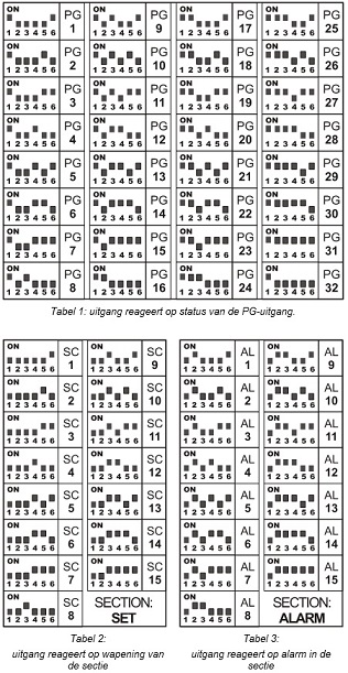
Table 1: Output responds to PG output status.
Table 2: output responds to section arming
Table 3: Output reacts to alarm in the section
Technical parameters
Power supply from the BUS of the control panel 12V (9 ...15V)
Standby current consumption (relay off/on) 5 mA / 25 mA
Current consumption for choice of cable 25 mA
Possible load of relay contacts:
max. excitation voltage 50 V AC / 60 V DC
max. excitation current max.2A
Min. excitation current 10 mA
Dimensions 70 x 38 x 15mm
Classification grade 2
according to EN 50131-1, EN 50131-3
Environment according to EN 50131-1 II. inside, general
Operating temperature range -10 to +40 °C
Further complies with EN 50130-4, EN 55022
This product has been designed and manufactured in accordance with the applicable provisions: Government Decree No. 616/2006 Coll., provided that it is used as intended. Original declaration of conformity can be found on www.jablotron.cz in the advice section.
Note: Although this product does not contain any harmful materials, do not dispose of it with household waste, but hand it in at the collection point designated for electronic waste.