
JA-113E
Service explanation for JA-113E
Wired code keypad with RFID
The access module is a component of the JABLOTRON JA-100 system. Thanks to the surface-mounted system, it is possible to put together a configuration that is tailored to the installation size and the wishes of the users. The product is intended for assembly by a trained technician with a valid Jablotron certificate.
The module contains an RFID reader and the 1st control segment (1). This configuration can be expanded with the desired number of JA-192E segments (up to max. 20 per configuration). The fold-out cover of the panel (6) can be removed if desired, in order to obtain permanent access. The control panel also works as a reader of contactless access cards / chips (RFID).
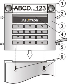
Figure: 1 – operating segment; 2 – segment keys; 3 – control panel module; 4 – illuminated activation key; 5 – clamps for opening; 6 – cover screws;
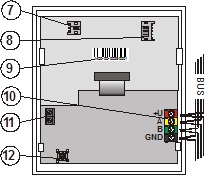
Image: 7 – audio module connector; 8 – connector control segments; 9 – serial number; 10 – connecting terminal audio module to control panel; 11 – terminal bus; 12 – tamper switch;
Installation
1. Press the four clamps on the sides one after the other (see fig. 1) and release the control panel from the plastic back wall.
2. When installing a subsequent operating segment, first remove the closing cap at the top of the 1st segment.
3. Remove the transparent covers from segments (by pulling forcefully on both sides at segment keys).
4. Always connect the guide wire of the segment to the connector of the previous segment and click them together (it is best to always rotate the guide wires by rotating the segment through 360° - this way the wires do not accidentally get caught between the plastic parts clamped). Install all desired control segments in the same way. Finally, replace the sealing cap (click in).
5. Pull the cable through the plastic back panel and screw the back panel into position with segments. When using several control segments, also fix the segments to the wall (choose the number of screws according to need).
6. Connect the bus cable to the connection terminal (11).
Before connecting the BUS, the system must be disconnected from the power supply.
7. Connect the segment supply to the internal connector of the control panel (8).
8. Click the control panel in the configuration.
9. Continue to follow the installation manual for the control panel. Basic Steps:
a. After power-up, the yellow signal light flashes because the control panel is not assigned to the system.
b. Select the desired position in the F-Link program on the Peripherals card and start the learning mode with the Read button.
c. Press the illuminated activation button (4), which causes the control panel to learn and the yellow light to go out.
10. After the assembly is complete, place the description labels in the segment cover caps and close the caps. Description labels are printed as part of the F-Link program (Peripherals card, at control panel position – Internal setting).
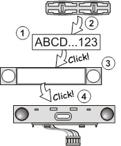
Image: place description label in the operating segment.
Set properties
This is done by the F-Link program – Card Peripherals. At control panel position Use internal setting. The current configuration appears, with the possibility to set its properties. Individual segments can be assigned the desired functions (section control, section state signaling, alarm sounding, PG output control, PG output state signaling, etc.). Details can be found in the F-Link program.
Change configuration
If the configuration of segments needs to be changed, pull them apart at the place of the connection, on the sides (on the side of the keys).
Technical parameters
Power supply from the control panel bus (9…15 V)
Current consumption in standby (rest) 10 mA
Current consumption for choice of cable 20 mA
Each added segment 0.5mA
RFID frequency 125 kHz
Operating temperature range -10 to +40 °C
Environment in accordance with CSN EN 50131-1 II. internal, general
Classification grade 2
in accordance with CSN EN 50131-1, CSN EN 50131-3,
Further complies with CSN ETSI EN 300330, CSN EN 50130-4,
CSN EN 55022, CSN EN 60950-1
Operating Conditions CTÚ No. VO-R/10/09.2010-11
Product JA-113E is designed and manufactured in accordance with the applicable provisions: Government Decree No. 426/2000 Coll. in the text of regulations promulgated later, provided that they are used for their intended purpose.
Note: Although this product does not contain any harmful materials, do not dispose of it with household waste, but hand it in at the collection point designated for electronic waste.
The module contains an RFID reader and the 1st control segment (1). This configuration can be expanded with the desired number of JA-192E segments (up to max. 20 per configuration). The fold-out cover of the panel (6) can be removed if desired, in order to obtain permanent access. The control panel also works as a reader of contactless access cards / chips (RFID).
Figure: 1 – operating segment; 2 – segment keys; 3 – control panel module; 4 – illuminated activation key; 5 – clamps for opening; 6 – cover screws;
Image: 7 – audio module connector; 8 – connector control segments; 9 – serial number; 10 – connecting terminal audio module to control panel; 11 – terminal bus; 12 – tamper switch;
Installation
1. Press the four clamps on the sides one after the other (see fig. 1) and release the control panel from the plastic back wall.
2. When installing a subsequent operating segment, first remove the closing cap at the top of the 1st segment.
3. Remove the transparent covers from segments (by pulling forcefully on both sides at segment keys).
4. Always connect the guide wire of the segment to the connector of the previous segment and click them together (it is best to always rotate the guide wires by rotating the segment through 360° - this way the wires do not accidentally get caught between the plastic parts clamped). Install all desired control segments in the same way. Finally, replace the sealing cap (click in).
5. Pull the cable through the plastic back panel and screw the back panel into position with segments. When using several control segments, also fix the segments to the wall (choose the number of screws according to need).
6. Connect the bus cable to the connection terminal (11).
Before connecting the BUS, the system must be disconnected from the power supply.
7. Connect the segment supply to the internal connector of the control panel (8).
8. Click the control panel in the configuration.
9. Continue to follow the installation manual for the control panel. Basic Steps:
a. After power-up, the yellow signal light flashes because the control panel is not assigned to the system.
b. Select the desired position in the F-Link program on the Peripherals card and start the learning mode with the Read button.
c. Press the illuminated activation button (4), which causes the control panel to learn and the yellow light to go out.
10. After the assembly is complete, place the description labels in the segment cover caps and close the caps. Description labels are printed as part of the F-Link program (Peripherals card, at control panel position – Internal setting).
Image: place description label in the operating segment.
Set properties
This is done by the F-Link program – Card Peripherals. At control panel position Use internal setting. The current configuration appears, with the possibility to set its properties. Individual segments can be assigned the desired functions (section control, section state signaling, alarm sounding, PG output control, PG output state signaling, etc.). Details can be found in the F-Link program.
Change configuration
If the configuration of segments needs to be changed, pull them apart at the place of the connection, on the sides (on the side of the keys).
Technical parameters
Power supply from the control panel bus (9…15 V)
Current consumption in standby (rest) 10 mA
Current consumption for choice of cable 20 mA
Each added segment 0.5mA
RFID frequency 125 kHz
Operating temperature range -10 to +40 °C
Environment in accordance with CSN EN 50131-1 II. internal, general
Classification grade 2
in accordance with CSN EN 50131-1, CSN EN 50131-3,
Further complies with CSN ETSI EN 300330, CSN EN 50130-4,
CSN EN 55022, CSN EN 60950-1
Operating Conditions CTÚ No. VO-R/10/09.2010-11
Product JA-113E is designed and manufactured in accordance with the applicable provisions: Government Decree No. 426/2000 Coll. in the text of regulations promulgated later, provided that they are used for their intended purpose.
Note: Although this product does not contain any harmful materials, do not dispose of it with household waste, but hand it in at the collection point designated for electronic waste.