
JA-110ST
Service explanation for JA-110ST
Wired fire detector
This wired detector is part of the JABLOTRON JA-100 alarm system. The sensor detects a fire hazard indoors. It is not intended for installation in an industrial environment. The detector consists of an optical smoke detector and a temperature sensor. The optical smoke detector is very sensitive to larger particles, which occur in dense smoke, less sensitive to small particles, which are created by burning liquids, such as alcohol. That is why a temperature sensor is also built in, which has a slower response, but is able to detect a fire with a small amount of smoke. The detector responds to the condition and reports it to the control panel. The product is intended for assembly by a trained technician with a valid Jablotron certificate.
Place detector
Smoke enters the detector through the flowing air – therefore it must be installed in a location where the air flows well thanks to natural thermal circulation (usually towards the ceiling). The detector can only be used in a closed interior. It is not suitable where the smoke can spread and cool (e.g. high ceilings - more than 5 m) - smoke will not reach the detector.
In flats, the detector must always be installed in the area leading to the exit (escape route) see figure 1. If the floor area in the flat exceeds 150 m2, another detector must be installed there, in another part of the house, see image 2.
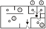
Figure 1
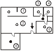
image 2
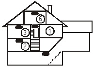
image 3
It is recommended to install a detector in every room where people sleep.
Place under flat ceilings
If possible, install the detector in the center of the room. Since a cold layer can form near the ceiling, the detectors must not be recessed into the ceiling. The fire detector must never be installed in a corner of the room (observe a distance of at least 0.5 m from the corner of the room, see figure 4). In the corners, the air circulates poorly.
Install under sloping ceilings
If the ceiling does not have a suitable flat surface (e.g. an attic room), the detector can be positioned as shown in Figure 5.
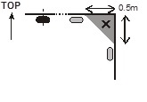
image 4
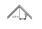
image 5
the middle of the room, the best place, a possible place
Walls, partitions, obstacles, ceilings with bare joists
The detector must be installed at least 0.5 m from a wall or obstacle. If the room is narrower than 1.2 m, the detector must be installed within the middle third of its width. If the room is divided into sections by means of furniture, scaffolding or half partitions, above which there is not more than 0.3 m from the ceiling, the individual sections should be considered as separate rooms. A free space of at least 0.5 m must be left in all directions under and around the detector. Any irregularity of the ceiling (such as a joist), with dimensions greater than 5% of the ceiling height, are considered to be walls where all the above will remain in effect.
Ventilation and air movement
Detectors may not be placed directly at the outlet of ventilation, air conditioning and the like. are installed. If the air is introduced through a perforated ceiling, the ceiling must be unperforated for 0.6 m in all directions around the detector.
Do not place detector:
? There, where the air flows poorly (niches, corners, ceiling ridges on A-roofs, etc.)
? there, where it is dusty, smoked or steam occurs
? in places where the air flows intensively (close to fans, heat sources, ventilation mouths, drafts, etc.)
? in kitchens and humid areas (steam, smoke and oily vapor can cause false alarms or detection failure)
? next to fluorescent or energy-saving lamps (electrical fault can cause a false alarm)
? in places with large numbers of small insects
Attention: Most often the detector is activated undesirably due to an incorrect installation location.
More detailed installation instructions can be found in CSN TS 54-14.
Installation
Follow the advice given in the previous paragraphs during installation.
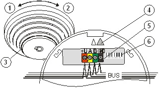
Figure 6: 1 – detach detector (pick up); 2 – fix detector (set up); 3 – optical signalling; 4 – orientation arrow for setting up; 5 – bus terminals; 6 – serial number
1. Open the detector cover by turning it to the left (1).
2. Pull the bus cable through and screw the plastic back panel onto the chosen location.
3. Connect the bus cable.
Before connecting the BUS, the system must be disconnected from the power supply.
4. Follow the installation manual of the control panel. Basic Steps:
a. After power-up, the yellow signal light flashes because the detector is not enrolled in the system.
b. Select the desired position in the F-Link program on the Peripherals card and start the learning mode with the Read button.
c. Place the detector on the plastic back wall. It can only be done in one position, indicated with arrows (4) on both plastic parts. Confirm by turning. As a result, the tamper sensor inside comes into contact and the detector learns. The yellow signal light (3) will go out.
Set detector properties
This is done by the F-Link program – Card Peripherals. Select Internal settings at the position of the detector. A dialog appears, in which you can set:
LED indication on: the red LED signaling activation can be turned off.
Mode of detection – smoke only, temperature only, smoke and temperature simultaneously, smoke or temperature.
Detector testing and maintenance
Operation of the detector can be checked with a test spray. Legislation recommends testing the detector once every 30 days. The detector must be regularly cleaned of dust, cobwebs and the like. be stripped.
Note : Never test the detector by creating an open fire in the object.
Indication of malfunction
The detector automatically checks its own operation. As soon as a malfunction is detected, the yellow control light lights up. In this case, remove the batteries for 1 minute and then reinsert them. If the light turns solid again after about 1 minute, take the detector to service.
Technical parameters
Power supply from the control panel BUS 12 V (9…15 V)
Current consumption at stand-by (rest) 5 mA
Current consumption for choice of cable 10 mA
Dimensions diameter 126 mm, height 50 mm
smoke detection optical light diffusion
smoke detector sensitivity m = 0.11 ¸ 0.13 dB/m cf. CSN EN 54-7
temperature detection class A2 according to CSN EN 54-5
alarm temperature 60°C to 70°C
range working temperatures -10°C to +80°C
Complies with CSN EN 54-5, CSN EN 54-7
further CSN EN 50130-4, CSN EN 55022
Place detector
Smoke enters the detector through the flowing air – therefore it must be installed in a location where the air flows well thanks to natural thermal circulation (usually towards the ceiling). The detector can only be used in a closed interior. It is not suitable where the smoke can spread and cool (e.g. high ceilings - more than 5 m) - smoke will not reach the detector.
In flats, the detector must always be installed in the area leading to the exit (escape route) see figure 1. If the floor area in the flat exceeds 150 m2, another detector must be installed there, in another part of the house, see image 2.
Figure 1
image 2
image 3
It is recommended to install a detector in every room where people sleep.
Place under flat ceilings
If possible, install the detector in the center of the room. Since a cold layer can form near the ceiling, the detectors must not be recessed into the ceiling. The fire detector must never be installed in a corner of the room (observe a distance of at least 0.5 m from the corner of the room, see figure 4). In the corners, the air circulates poorly.
Install under sloping ceilings
If the ceiling does not have a suitable flat surface (e.g. an attic room), the detector can be positioned as shown in Figure 5.
image 4
image 5
the middle of the room, the best place, a possible place
Walls, partitions, obstacles, ceilings with bare joists
The detector must be installed at least 0.5 m from a wall or obstacle. If the room is narrower than 1.2 m, the detector must be installed within the middle third of its width. If the room is divided into sections by means of furniture, scaffolding or half partitions, above which there is not more than 0.3 m from the ceiling, the individual sections should be considered as separate rooms. A free space of at least 0.5 m must be left in all directions under and around the detector. Any irregularity of the ceiling (such as a joist), with dimensions greater than 5% of the ceiling height, are considered to be walls where all the above will remain in effect.
Ventilation and air movement
Detectors may not be placed directly at the outlet of ventilation, air conditioning and the like. are installed. If the air is introduced through a perforated ceiling, the ceiling must be unperforated for 0.6 m in all directions around the detector.
Do not place detector:
? There, where the air flows poorly (niches, corners, ceiling ridges on A-roofs, etc.)
? there, where it is dusty, smoked or steam occurs
? in places where the air flows intensively (close to fans, heat sources, ventilation mouths, drafts, etc.)
? in kitchens and humid areas (steam, smoke and oily vapor can cause false alarms or detection failure)
? next to fluorescent or energy-saving lamps (electrical fault can cause a false alarm)
? in places with large numbers of small insects
Attention: Most often the detector is activated undesirably due to an incorrect installation location.
More detailed installation instructions can be found in CSN TS 54-14.
Installation
Follow the advice given in the previous paragraphs during installation.
Figure 6: 1 – detach detector (pick up); 2 – fix detector (set up); 3 – optical signalling; 4 – orientation arrow for setting up; 5 – bus terminals; 6 – serial number
1. Open the detector cover by turning it to the left (1).
2. Pull the bus cable through and screw the plastic back panel onto the chosen location.
3. Connect the bus cable.
Before connecting the BUS, the system must be disconnected from the power supply.
4. Follow the installation manual of the control panel. Basic Steps:
a. After power-up, the yellow signal light flashes because the detector is not enrolled in the system.
b. Select the desired position in the F-Link program on the Peripherals card and start the learning mode with the Read button.
c. Place the detector on the plastic back wall. It can only be done in one position, indicated with arrows (4) on both plastic parts. Confirm by turning. As a result, the tamper sensor inside comes into contact and the detector learns. The yellow signal light (3) will go out.
Set detector properties
This is done by the F-Link program – Card Peripherals. Select Internal settings at the position of the detector. A dialog appears, in which you can set:
LED indication on: the red LED signaling activation can be turned off.
Mode of detection – smoke only, temperature only, smoke and temperature simultaneously, smoke or temperature.
Detector testing and maintenance
Operation of the detector can be checked with a test spray. Legislation recommends testing the detector once every 30 days. The detector must be regularly cleaned of dust, cobwebs and the like. be stripped.
Note : Never test the detector by creating an open fire in the object.
Indication of malfunction
The detector automatically checks its own operation. As soon as a malfunction is detected, the yellow control light lights up. In this case, remove the batteries for 1 minute and then reinsert them. If the light turns solid again after about 1 minute, take the detector to service.
Technical parameters
Power supply from the control panel BUS 12 V (9…15 V)
Current consumption at stand-by (rest) 5 mA
Current consumption for choice of cable 10 mA
Dimensions diameter 126 mm, height 50 mm
smoke detection optical light diffusion
smoke detector sensitivity m = 0.11 ¸ 0.13 dB/m cf. CSN EN 54-7
temperature detection class A2 according to CSN EN 54-5
alarm temperature 60°C to 70°C
range working temperatures -10°C to +80°C
Complies with CSN EN 54-5, CSN EN 54-7
further CSN EN 50130-4, CSN EN 55022