
JA-180PB
Service explanation for JA-180PB
Wireless PIR and Glass Break combined detector
This product is part of the Jablotron 100 series alarm system. The sensor contains two independent detectors (it learns 2 addresses in the control panel). A PIR sensor is used to detect the movement of people. Breaking of glass surfaces that are part of the monitored room is detected by changes in air pressure and characteristic sounds of glass breakage. The detector is intended for indoor use, communicates via the wireless and secure Jablotron protocol and is battery powered. 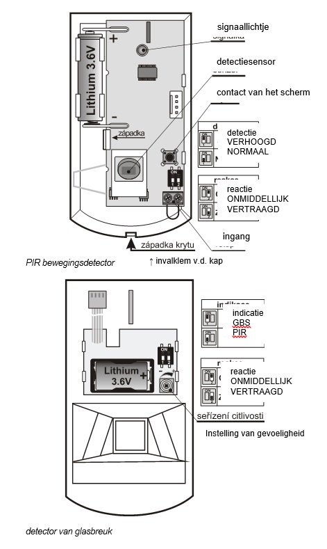
Installation
This product must be installed by a trained technician with valid manufacturer's certificate. The detector can be installed on a wall or in a corner of the room. In the field of view of the PIR sensor there must be no objects that change temperature quickly (electric heaters, gas appliances and the like), no objects with a temperature approaching human body temperature and that move (e.g. billowing curtains, made warm by a radiator or the sun) and no pets. It is not recommended to install the detector opposite windows or reflectors.
There should be no ventilation mouth, fan or other sources of air pressure changes or intense noise near the glass break detector. There must also be no sources of vibration or blows/claps in the room to be monitored.
In front of the detector there must be no obstacles that obstruct its view and it must not be installed near metal objects (they obscure radio communication).
Attention: the most common cause of unwanted detector activation is an incorrectly chosen location. The detector must not be switched on to monitor if people or animals are moving in the room. When mounting, do not touch the PIR sensor in the detector.
1. Open the lid of the detector (press the snap clip) and disconnect the cable from the lid module (glass break detector)
2. Take out the module from the PIR detector - held by the drop-in clamp
3. Push through the holes for screws in the plastic back panel (at least one screw must be in the segment for detecting the tear-off of the assembly)
4. Screw the plastic rear wall, about 2.5 m high from the floor (vertically, with the plunge clamp of the lid down)
5. Replace the PIR detector module (with the sensor facing the plunger of the cover)
6. Leave the battery disconnected and the lid open. Proceed according to the installation manual of the control panel (receiver). Basic Steps:
a. Switch the control panel to service and activate learning mode with key 1
b. Connect the battery to the PIR detector - this will start the PIR detector to learn
c. Connect the battery to the glassbreak detector and then connect its cable to the plate of the PIR detector - this will teach the detector at the next free address (learn the glassbreak detector only after the PIR has been learned)
d. End the learning mode with the # key
To comply with the EN 50131-2-2 standard, the plunge clamp of the cover must be secured by the supplied screw.
If you are going to learn the detector in the receiver after the batteries have already been connected, first disconnect both batteries, then press and release the cover contact (the residual energy will be used up) and only then execute the learn mode.
After connecting the batteries, the detector needs about 2 minutes to stabilize. During this period, its signal light remains permanently on.
Adjustable switches of PIR module
Switch 1: determines the degree of immunity against false alarms. Position OFF combines good immunity with fast response. Position ON increases sensor immunity at the expense of speed (to be used in problematic installations).
Note: The most common cause of unwanted activation is incorrect detector placement.
Switch 2: DEL/INS determines whether the detector is on the entrance way to the house and provides an exit and entry delay = position OFF. In the ON position, the detector calls for an immediate response from the armed control panel. The switch is only meaningful when used with the Jablotron control panel with set response, of course. If a different reaction has been set in the detector's control panel, or you are using the detector with a JA-182N or JA-180N receiver, the switch has no meaning.
When the lid is opened, the detector always responds with a tamper signal.
Adjustable switches of the glass break module
Switch 1: determines what will be indicated by the signal light and the system in test mode – the movement or breaking of glass (see Testing the Detector). The switch only affects the behavior of the detector for 15min. after closing its lid.
Note: Although both detectors are housed in a housing, they operate independently. Each is learned for its own address and each can have its own response set (by switches or control panel setting)
Switch 2 determines the mode of response to activation of the glass break detector. In the OFF position, the system provides an entry and exit delay (delayed response is recommended if the detector is installed near the entrance door). In the ON position, detector activation triggers an immediate alarm.
The switch is only meaningful when used with the Jablotron control panel with NATUR response set. If a different reaction has been set in the detector's control panel, or you are using the detector with a JA-182N or JA-180N receiver, the switch has no meaning.
Detector testing
For 15 minutes after closing the lid, the signal light indicates activation of the detector selected by the PIR/GBS switch. The control panel allows, in service mode, to check signals from detectors, including the measurement of their quality.
Switch 1
- in the ON position, a short flash of the signal light indicates the air pressure change (clap against the glass), a long flash indicates the alarm by breaking the glass (transfer to the control panel).
- in the OFF position, a short flash of the signal light indicates a detected movement (start of analysis), a long flash indicates the alarm (a long flash is also indicated if the glass has been broken).
Testing and setting up glass break detector:
• Strike successively against all glass surfaces in the area to be monitored with a suitable tool or by hand in a protective glove (so that the glass is noticeably deformed, but does not break)
• After glass deformation (pressure change in the chamber) the detector should respond with a short flash of the light (switch should be in the BMS position).
• Sensitivity to pressure changes can be adjusted by the trimmer on the module in the lid (clockwise the sensitivity increases - an unnecessarily high sensitivity shortens the battery life).
• The complex operation of the detector can be verified by the GBT-212 tester. This generates the sound of breaking glass after a blow against the glass.
• If there is an automatic device in the monitored room that emits noise (air conditioning, heating, fax, cooling units, etc.) check that the glass break detector is not activated by this activity.
Detection characteristic PIR sensor
The detector is supplied with a 120°/12m lens from the factory. The room is monitored by 3 fans (curtain fields) – see the following figure. 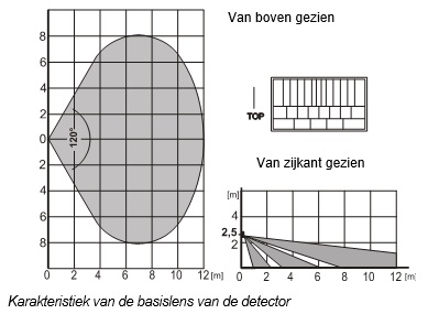
Characteristic of the base lens of the detector
Characteristic can be changed by using an alternative lens: 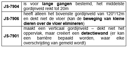
JS-7904 is intended for long corridors, the middle curtain field reaches up to 20m
JS-7906 only has the top curtain field of 120°/12m and does not cover the floor (can eliminate the movement of small animals across the floor)
JS-7901 creates a vertical curtain - does not cover the surface, but creates a detection wall (a barrier can be defined, where any violation is reported)
Note: After replacing the lens, check that the detector covers the room properly (an incorrectly installed lens may cause a detection error).
Choose a sleep period of 5 minutes / 1 minute for the PIR sensor
15 minutes after closing the lid, the PIR sensor goes into energy saving mode. If it detects a movement, the control panel informs and does not react to the movement for the next 5 minutes (sensor sleeps). At the end of this period, the sensor wakes up and monitors continuously until the next movement in the room, etc.
The sleep period of the sensor can be shortened to 1 minute by pressing the lid ignition switch when connecting the battery of the PIR detector (if you connect the battery without pressing the lid switch, the sleep period will be set to 5 minutes ).
The glass break detector is ready to report an alarm at all times.
Auxiliary input for wires
For example, the input can be used for the magnetic door/window detector. The activation (opening of the terminals) has the same effect as the movement for the detector.
The cable connected to the terminals may be a maximum of 3m long, it is recommended to use a shielded cable.
If the input is not used, the terminals must be connected. 
Detection characteristic of the glass break detector
The glass break detector has an almost spherical detection characteristic. For example, it is able to detect the breaking of glass up to 9 m, see the following image (the glass area must be at least 60 x 60 cm - for smaller windows the detection distance will be shorter). The prerequisite for proper operation is that the glass surface forms the shell of the enclosed space in which the detector is installed. The detector responds to the breaking of all types of glass, including the glass with a laminate foil.
Note: the detector is not able to accurately detect the cutting of an opening in the glass by a glass cutter. It is therefore recommended to have the valuables monitored directly behind the glass with a motion detector. 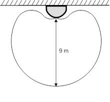
Range characteristic of the detector – viewed from above or from the side
Replace batteries in the detector
The product contains 2 batteries and continuously monitors their status. If they become weaker, the user is informed (possibly also the service technician). The detector continues to operate and also indicates movement by a short flash of the signal light. We recommend replacing both batteries within 2 weeks of the notification. The batteries are replaced by a technician in service mode. After the batteries have been replaced, the sensor needs about 2 minutes to stabilize - its light stays on. After replacing batteries, test the operation of both sensors (you choose by the PIR / BMS switch which detector is indicated by the signal light for 15 min after closing the lid).
If a weak battery is inserted in the detector, its signal light will flash for approx. 1 minute. After that, the detector will work, but will report a low battery.
Do not dispose of a used battery with household waste, but dispose of it with chemical waste.
Remove detector from system
The system reports any loss of the detector. Therefore, if you intentionally disassemble a detector, it must be cleared from both respective addresses in the control panel.
Technical parameters
Power supply PIR part lithium battery type LS(T)14500 (3.6 V AA / 2.4Ah)
Power supply GBS part lithium battery type LS(T)14250 (3.6 V ½ AA / 1.2Ah)
Typical battery life approx. 3 years (PIR sensor sleeps 5min.)
Communication band 868.1 MHz, Jablotron protocol
Communication range approx. 300m (direct visibility)
Recommended installation height 2.5 m above the floor
Detection angle / detection coverage PIR sensor 120° / 12 m (with base lens)
Glass breakage detection distance: 9m (glass min. 60 x 60cm)
Environment in accordance with CSN EN 50131-1 II. inside, general
Operating temperature range -10 to +40 °C
Dimensions, weight 110 x 60 x 55 mm, 120 g
Classification according to CSN EN 50131-1, CSN EN 50131-2-2, CSN EN 50131-5-3
grade 2
Complies with CSN ETSI EN 300220, CSN EN 50130-4, CSN EN 55022,
CSN EN 60950-1
Operating conditions CTÚ VO-R/10/06.2009-9
The detector is designed and manufactured in accordance with the applicable provisions: Government Decree No. 426/2000 Coll., provided that it is used according to its intended purpose. Original declaration of conformity can be found on www.jablotron.cz in the advice (support) section.
Note: Although this product does not contain any harmful materials, do not dispose of it with household waste, but hand it in at the collection point designated for electronic waste.