
JA-110P
Service explanation for JA-110P
Wired PIR motion detector
This product is part of the JABLOTRON JA-100 alarm system. It detects the movement of people within buildings. Its detection characteristic can be changed by using an alternative lens. False alarm immunity is optional, in two levels. The detector has a pulse response (only reports its own activation). The product is intended for assembly by a trained technician with a valid Jablotron certificate.
Installation
The detector can be installed on a wall or in a corner of the room. It is better if there are no objects that change temperature quickly (electric heaters, gas appliances, etc.), no moving objects (e.g. billowing curtains above a radiator) or pets within his reach. It is not recommended to install the detector opposite windows or reflectors, not even where the air flows (ventilation, air conditioning, drafts, non-closing doors, etc.). There must be no objects in front of the detector that obstruct the view.
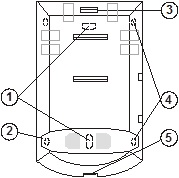
Picture: 1 - holes for mounting on a flat wall; 2, 4 – holes for corner mounting; 3 – click clamp of the electronics board; 5 – snap clip of the cover;
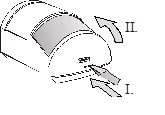
1. Open the detector cover (by pressing the snap clip 5). Do not touch the PIR sensor (11) inside - so as not to damage it.
2. Take out the electronics – it is attached to the click clamp 3.
3. Make holes in the plastic back wall for screws and cable. The recommended height for installing the detector is 2.5 m above the floor.
4. Pull the bus cable through and screw the plastic back panel into place (vertically, with the cover clip down).
Before connecting the BUS, the system must be disconnected from the power supply.
5. Replace the electronics and connect the cable in the clamps (8).
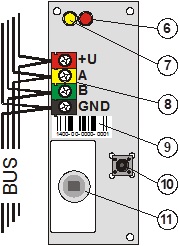
Figure: 6 – red activation signal light; 7 – yellow fault indicator light; 8 – bus terminals; 9 – serial number; 10 – tamper switch; 11 – PIR sensor;
6. Follow the installation manual of the control panel. Basic Steps:
a. After switching on, the yellow signal light (7) flashes because the detector is not assigned to the system.
b. Select the desired position in the F-Link program on the Peripherals card and start the learning mode with the Read button.
c. Press the tamper switch in the detector (10) - this will teach the detector and the yellow signal light will go out. Note - the module occupies 2 consecutive positions (one input each).
7. Close the detector cover.
Set detector properties
This is done by the F-Link program – Card Peripherals. At the position of the detector (first or second) choose the Internal settings. A dialog appears, in which you can set:
Immunity Level: Determines immunity against false alarms. By default (from the factory) basic immunity is combined with a fast response. The Elevated level provides better immunity, but the detector responds more slowly.
LED indication of movement: allows to disable the indication of movement by the red LED.
Detection characteristic
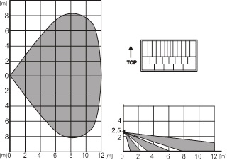
The detector is supplied with a 110°/12m lens from the factory. The room is covered by 3 fans (curtain fields) – see the next picture.
The characteristic can be changed by using an alternative lens:
JS-7904 is intended for long corridors, has a range of up to 20m
With this lens the increased immunity cannot be used!
JS-7906 only has the top fan of 120°/12m and does not cover the floor (can eliminate movement of small animals across the floor)
JS-7901 vertical curtain field – does not cover the surface, but creates a detection wall (a barrier can be defined, any violation is reported)
Note: After replacing the lens, check that the detector covers the room properly (improperly installed lens may cause a detection error).
Technical parameters
Power supply from the control panel BUS 12 V (9 ... 15 V)
Current consumption at stand-by (rest) 5 mA
Current consumption for choice of cable 5 mA
Recommended installation height 2.5 m above the floor
Detection angle / detection coverage 110° / 12 m (with base lens)
Dimensions 95 x 60 x 55mm
Classification grade 2
in accordance with CSN EN 50131-1, CSN EN 50131-2-2
Environment in accordance with CSN EN 50131-1 II. inside, general
Operating temperature range -10 to +40 °C
Further complies with CSN EN 50130-4, CSN EN 55022
Installation
The detector can be installed on a wall or in a corner of the room. It is better if there are no objects that change temperature quickly (electric heaters, gas appliances, etc.), no moving objects (e.g. billowing curtains above a radiator) or pets within his reach. It is not recommended to install the detector opposite windows or reflectors, not even where the air flows (ventilation, air conditioning, drafts, non-closing doors, etc.). There must be no objects in front of the detector that obstruct the view.
Picture: 1 - holes for mounting on a flat wall; 2, 4 – holes for corner mounting; 3 – click clamp of the electronics board; 5 – snap clip of the cover;
1. Open the detector cover (by pressing the snap clip 5). Do not touch the PIR sensor (11) inside - so as not to damage it.
2. Take out the electronics – it is attached to the click clamp 3.
3. Make holes in the plastic back wall for screws and cable. The recommended height for installing the detector is 2.5 m above the floor.
4. Pull the bus cable through and screw the plastic back panel into place (vertically, with the cover clip down).
Before connecting the BUS, the system must be disconnected from the power supply.
5. Replace the electronics and connect the cable in the clamps (8).
Figure: 6 – red activation signal light; 7 – yellow fault indicator light; 8 – bus terminals; 9 – serial number; 10 – tamper switch; 11 – PIR sensor;
6. Follow the installation manual of the control panel. Basic Steps:
a. After switching on, the yellow signal light (7) flashes because the detector is not assigned to the system.
b. Select the desired position in the F-Link program on the Peripherals card and start the learning mode with the Read button.
c. Press the tamper switch in the detector (10) - this will teach the detector and the yellow signal light will go out. Note - the module occupies 2 consecutive positions (one input each).
7. Close the detector cover.
Set detector properties
This is done by the F-Link program – Card Peripherals. At the position of the detector (first or second) choose the Internal settings. A dialog appears, in which you can set:
Immunity Level: Determines immunity against false alarms. By default (from the factory) basic immunity is combined with a fast response. The Elevated level provides better immunity, but the detector responds more slowly.
LED indication of movement: allows to disable the indication of movement by the red LED.
Detection characteristic
The detector is supplied with a 110°/12m lens from the factory. The room is covered by 3 fans (curtain fields) – see the next picture.
The characteristic can be changed by using an alternative lens:
JS-7904 is intended for long corridors, has a range of up to 20m
With this lens the increased immunity cannot be used!
JS-7906 only has the top fan of 120°/12m and does not cover the floor (can eliminate movement of small animals across the floor)
JS-7901 vertical curtain field – does not cover the surface, but creates a detection wall (a barrier can be defined, any violation is reported)
Note: After replacing the lens, check that the detector covers the room properly (improperly installed lens may cause a detection error).
Technical parameters
Power supply from the control panel BUS 12 V (9 ... 15 V)
Current consumption at stand-by (rest) 5 mA
Current consumption for choice of cable 5 mA
Recommended installation height 2.5 m above the floor
Detection angle / detection coverage 110° / 12 m (with base lens)
Dimensions 95 x 60 x 55mm
Classification grade 2
in accordance with CSN EN 50131-1, CSN EN 50131-2-2
Environment in accordance with CSN EN 50131-1 II. inside, general
Operating temperature range -10 to +40 °C
Further complies with CSN EN 50130-4, CSN EN 55022