
JA-110M
Service explanation for JA-110M
BUS module for magnet detector connection (2 inputs)
This product is part of the JABLOTRON JA-100 alarm system. It makes it possible to connect two magnetic contacts via two independent inputs with the possibility of setting the properties. The module occupies two positions in the system. The detector responds to the condition (it reports activation and deactivation). The product is intended for assembly by a trained technician with a valid Jablotron certificate
Installation
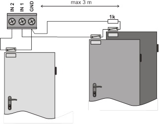
Choose a location for the module so that the cables to the detectors are a maximum of 3 m long.
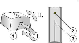
Figure: 1 – hood snap clip; 2 – yellow fault indicator light; 3 – red signal light of the activation inputs;
1. Open the cover and remove the electronics board (by pressing the snap clip)
2. Pull the cables through the plastic back wall and screw it in place.
Before connecting the BUS, the system must be disconnected from the power supply.
3. Replace the electronics and connect the cables to the terminals.

Figure: 4 – yellow signal light of the fault; 5 – red signal light of the activation inputs; 6 – bus terminals; 7 - tamper switch; 8 – detector terminals; 9 – serial number;
4. If you want to use a balanced loop for higher protection of the detectors' supply cables, connect a 1k resistor in series with the detector (see the following figure). The balancing function must be enabled when setting the properties.
5. Follow the installation manual of the control panel. Basic Steps:
a. After power-up, the yellow signal light flashes because the detector is not enrolled in the system.
b. Select the desired position in the F-Link program on the Peripherals card and start the learning mode with the Read button.
c. Press the tamper switch in the module (7) - this will teach the detector and the yellow signal light will go out. Note - the module occupies 2 consecutive positions (one input each).
6. Close the module cover.
Set module properties
This is done by the F-Link program – Card Peripherals. At the position of the module (first or second), choose the Internal settings. A dialog appears, in which you can set:
Response of the input 1(2): Off – does not respond (the input can be turned off completely), Unbalanced – responds to contact disconnection, Balanced – 1k resistance is assigned in series with the contact. The activation occurs when the resistance drops below 700 Ohm or rises above 1300 Ohm.
Delay of response on entry: time filter to improve immunity against false activation – setting of 0.1s ... 300s determines how long the INP1(2) input must be active before it is activated in the control panel.
Reverse Response of Input: The input is set from the factory to respond to disconnection from the circuit (NC). You can also set the response to making contact (NO).
LED indication is on: it allows to turn off the red signal light of the activation of each input.
Technical parameters
Power supply from the control panel BUS 12 V (9…15 V)
Current consumption at stand-by (rest) 5 mA
Current consumption for choice of cable 5 mA
max. length of connection cable from input to detector 3 m
Dimensions 100 x 40 x 24mm
Classification grade 2
in accordance with CSN EN 50131-1, CSN EN 50131-3
Environment in accordance with CSN EN 50131-1 II. inside, general
Operating temperature range -10 to +40 °C
Further complies with CSN EN 50130-4, CSN EN 55022
Installation
Choose a location for the module so that the cables to the detectors are a maximum of 3 m long.
Figure: 1 – hood snap clip; 2 – yellow fault indicator light; 3 – red signal light of the activation inputs;
1. Open the cover and remove the electronics board (by pressing the snap clip)
2. Pull the cables through the plastic back wall and screw it in place.
Before connecting the BUS, the system must be disconnected from the power supply.
3. Replace the electronics and connect the cables to the terminals.
Figure: 4 – yellow signal light of the fault; 5 – red signal light of the activation inputs; 6 – bus terminals; 7 - tamper switch; 8 – detector terminals; 9 – serial number;
4. If you want to use a balanced loop for higher protection of the detectors' supply cables, connect a 1k resistor in series with the detector (see the following figure). The balancing function must be enabled when setting the properties.
5. Follow the installation manual of the control panel. Basic Steps:
a. After power-up, the yellow signal light flashes because the detector is not enrolled in the system.
b. Select the desired position in the F-Link program on the Peripherals card and start the learning mode with the Read button.
c. Press the tamper switch in the module (7) - this will teach the detector and the yellow signal light will go out. Note - the module occupies 2 consecutive positions (one input each).
6. Close the module cover.
Set module properties
This is done by the F-Link program – Card Peripherals. At the position of the module (first or second), choose the Internal settings. A dialog appears, in which you can set:
Response of the input 1(2): Off – does not respond (the input can be turned off completely), Unbalanced – responds to contact disconnection, Balanced – 1k resistance is assigned in series with the contact. The activation occurs when the resistance drops below 700 Ohm or rises above 1300 Ohm.
Delay of response on entry: time filter to improve immunity against false activation – setting of 0.1s ... 300s determines how long the INP1(2) input must be active before it is activated in the control panel.
Reverse Response of Input: The input is set from the factory to respond to disconnection from the circuit (NC). You can also set the response to making contact (NO).
LED indication is on: it allows to turn off the red signal light of the activation of each input.
Technical parameters
Power supply from the control panel BUS 12 V (9…15 V)
Current consumption at stand-by (rest) 5 mA
Current consumption for choice of cable 5 mA
max. length of connection cable from input to detector 3 m
Dimensions 100 x 40 x 24mm
Classification grade 2
in accordance with CSN EN 50131-1, CSN EN 50131-3
Environment in accordance with CSN EN 50131-1 II. inside, general
Operating temperature range -10 to +40 °C
Further complies with CSN EN 50130-4, CSN EN 55022